

Looking at Seam Tracking means looking at a variety of possible solutions. Depending on your process, material, and cycle time needs, the right solution will usually present itself over time.
But with if you aren't aware of ALL the solutions available?
Or just know about a couple?
What are the upsides and downsides of all the different seam tracking solutions available?
And are certain seam tracking solutions just not right for me based on what I'm welding?
Sensor technology presents a lot of possibilities to your welding operation. Some are low-cost and limited in capability and others involve large investment and thoughtful design - with huge upside is cost savings.
Laser Pointer and Manual Slides
Fixed pointers with manual slides are very basic versions of Seam Tracking. This is literally a fixed pointer of some sort. It can be a spring on a rod or a laser pointer coming down to provide a visual optic.
However configured, this option requires the operator to drive a set of slides to keep the weld on the joint. This is as cost-friendly as Seam Tracking gets for automated welding production.
Laser Pointing comes with major room for operator error. It's unavoidable. You will rely on your operator to make sure the mechanical setup is correct and the pointer is on the right spot.
Cycle time is also a major issue. Why do you invest in Seam Tracking? To save on cycle time for starters. When you rely on an operator to make decisions with slides on the fly, are you saving the time you're expecting for the investment?
If you have an operator who can manage this type of Seam Tracking with consistency and effectiveness, don't let him or her go. Otherwise, you likely can get better results and investment return going with a more advanced option.
Touch Sensing
Touch sensing in where the robot applies a small amount of voltage to either the welding nozzle or the weld wire. They both function the same way, with the only difference being the way each method translates data to the robot.
Through the voltage, the robot will come up to the work material, touch it, a short will occur, then the robot will record that position of where that recorded value is and tell the robot where the surface is.
Most occasions require at least 2 touches per joint to find the location - a vertical and horizontal surface. The robot will connect those search vectors and triangulate where the weld joint is.
![]() On corner or outside edge joints, a third touch from the robot is typically necessary to get all the right positions to allow the robot to find and 'track' the joint.
On corner or outside edge joints, a third touch from the robot is typically necessary to get all the right positions to allow the robot to find and 'track' the joint.
Touch sensing is useful as a low-cost joint tracking solution. It's a simple software-based solution you're able to apply from the teach pendant without additional systems. One of the other main benefits of touch sensing is you are able to get into tight areas because there's no additional hardware other than your robot torch nozzle impeding the joint being reached.
Touch sensing does have several limitations that make it a remedial solution for joint sensing and seam tracking. The first being that touch sensing is a slow process that adds 3 to 5 seconds per search vector. So, if you are touch sensing on a 2D part, you potentially add 6 to 10 seconds to the weld cycle, and if you are touch sensing a 3D part up to 15 seconds of time is added to the cycle time per arc start and arc end.
The number of failure points with touch sensing is also far greater than other solutions. Conditions like bent wire or dirty and scaly material make it hard to run touch sensing consistently. Touch sensing is only intended to find your arc start or arc end, and doesn't help with part variance throughout the length of the weld, so it won't compensate for inconsistent fixturing or tooling of the part.
Touch sensing is also limited by weld joint type. Fillet and lap joints are the most common and recommended joints, but even with lap joints, you have to consider material thickness. Anything less than 5 mm (1/4") can become problematic to perform touch sensing because the material thickness of the upper plate can potentially be missed by the wire - causing you to overshoot the part, or you can hit the lower plate and get a false reading.
Your robot torch also needs both a wire brake and a wire cutter outfitted in the torch package to cut the wire at a known distance away from the tip so your readings are consistent throughout the process.
Touch sensing also requires clean edges. Tack welds or poorly trimmed parts can produce false readings.
Through Arc Seam Tracking
Through the Arc Seam Tracking (TAST) is the second phase you would apply with Touch Sensing. After touch sensing, you find your arc start and arc end, then apply TAST to seam track on the Z and Y axis of the joint.
TAST is a good fit for thicker material. It also requires a weaving process. As the wire transitions from one side to the other side of the joint, the voltage is changing. This happens due to the stick-out of the wire decreasing on the change to the tip to work distance. This allows the robot to interpret the change in voltage and adjust the taught path, maintaining proper weld position in the joint.
![]() TAST is requires 5 mm (1/4") or thicker to be stable. To do TAST at a lower thickness is not recommended. I've never witnessed TAST on material thinner than 1/4" in all my years working with seam tracking applications. Doing TAST on thin material can risk wormtracking or snaking the weld, which can reduce weld integrity.
TAST is requires 5 mm (1/4") or thicker to be stable. To do TAST at a lower thickness is not recommended. I've never witnessed TAST on material thinner than 1/4" in all my years working with seam tracking applications. Doing TAST on thin material can risk wormtracking or snaking the weld, which can reduce weld integrity.
Another reason TAST on thinner material is not recommended is the tendency of TAST to wash or remove the shoulder of the upper plate. This washing won't allow for a significant voltage change, causing the robot to search - which is where the wormtracking risk emerges.
One other limitation to TAST is you have to add cycle time because it requires the robot to weave through the joint. Typically travel speeds for TAST is limited to 35 - 50 inches per minute. TAST is likewise process limited to MIG applications only - it's not possible with TIG or Plasma.
Lastly, TAST is limited to use for mild or stainless steel. Voltages are not consistent enough with aluminum to reliably do TAST. The conditions of the material is also important. Part cleanliness, mill scale, or rust has an impact on the parameter sets because you set up the criteria of what you want for voltage change. A 2% voltage change on a negative Y due to mill scale or rust on the metal will produce inconsistent characteristics for TAST.
Dry runs are also not possible with TAST as the robot has to be welding to track. Tacks are likewise problematic because when you run over a tack, the stick-out changes, so the robot loses tracking until it comes out the other side of the tack weld.
2D Vision Systems
Think of 2D vision like a camera. It takes a reference image of an ideal part before striking an arc and matches the reference image to each new subsequent part - detecting any offsets and adjusting the weld path. It only gives a black and white image and transmits where that image is located on it's surface. 2D can't determine height or depth, and is not considered a reliable process for seam tracking.
Joints like V-joints and lap joints are very problematic for 2D Vision because it cannot determine depth on these types of weld joints. Shiny materials like aluminum are also problematic for 2D systems because they cause interference.
Usually, 2D is used for identification of parts instead of tracking. It is a vision-based system, so outside light interference is very critical to the performance of the optic. Also, the camera lens is sensitive to damage from weld spatter and arc light.
Tactile Seam Tracking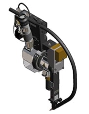
Tactile is a physical contact probe that touches the material. Tactile is typically used in hard automation and some laser brazing applications, and not a recommended seam tracking application for a 6-axis robot. Tactile rides a tip or probe inside the welding joint, and detects deviations from the edge that it touches and the original source and adjusts it's cross slides accordingly to position itself correctly over the weld seam.
Tactile Seam Tracking has a very simple operating function that can be applied to a variety of processes, including sub-arc, open arc, and brazing, which makes it a very versatile form of seam tracking. Tactile is also not limited by any kind of material, so you can tactile seam track anything from stainless steel to aluminum material without the system being affected in any way.
Maintenance is an important part of keeping tactile seam tracking system working correctly. The wearing out of parts happens often with tactile system because the tip is in constant contact with the joint surface. As your tactile probe wears and gets shorter it will have the tendency to drive your welding tool forward closer to the joint, which can produce poor welds or damage the front end of the torch entirely. It's important to check the probe for wear to make sure that it is properly standing off the torch to get the high quality weld possible.
Conditions like weld spatter and cable management are other items to inspect and maintain more often than contact-free solutions.
Tactile solutions also don't adjust to tack welds well. Tacks can lift the probe over the tack weld and lead the arc in the same direction as opposed to letting the weld torch weld through the tack as is generally recommended.
Tactile is also not adaptive. These sorts of systems follows the joint line and don't account for mismatches or gap dimensions as a result of tooling. Area calculations are also not possible. A tactile probe is going to lock into a groove and follow it with very few deviations. A great enough variance in a groove or a large enough tack weld can take the probe out of it's desired track.
Weld profiles like butt welds are difficult to perform tactile seam tracking on without a gap. Non-linear welds that force the probe to move sharply in a direction are not ideal scenario for Tactile Seam Tracking applications; it works well with large cylinder welds or pipe welding.
Travel speed is another limitation to Tactile Seam Tracking, as it typically moves at lower speeds which can slow your cycle time.
Comparing tactile to vision based seam tracking is a matter of one being a contact-based approach and the other non-contact . While it being a mechanical setup it is generally a lower up front capital investment, Tactile Seam Tracking systems in open and sub-arc applications require more maintenance as it is a mechanical process, which long term can make it a less cost-effective solution due the measuring body's sensitivity and constant wearing of components.
3D Laser Seam Tracking
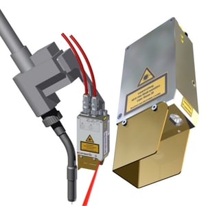 Also known as Optical or Vision Seam Tracking, a 3D Laser Seam Tracking system uses laser triangulation. 3D Seam Tracking is able to be used on both hard automation and robotic systems effective with the right software package.
Conceptually, Laser Seam Tracking involves a laser beam shooting out of a device, hitting a surface, reflecting off the surface, bouncing back into the sensor, and the sensor picks up where the beams hit. So with Laser Seam Tracking, the sensor knows the distance between the laser emitter and the sensor on the camera, allowing it to triangulate the position of that material it bounced off.
In essence, you get an image of the Z (height) and Y (across) of the joint, so the sensor knows the image that it bounced off of was X (distance) dimension away from the sensor ray, and the feature that it's selecting is either positive or negative in the field of view across the Y direction.
Laser Seam Tracking does not know X direction, or how long the part is. This is why you partner the device to a control system, and the control system defines the X value - a process known as calibration. After calibration, your seam tracking system knows X, Y, and Z location throughout the weld process.![]()
Any seam tracking solution to the weld process adds to the cycle time, but Optical Seam Tracking adds the least - typically around a quarter of a second (.25 seconds) to the weld cycle per scan.
It also moves the fastest. Optical Seam Tracking can go up to 200 inches per minute, so it doesn't limit the robot or gantry speed if high travel speeds are required. Optical Seam Tracking can also be used in processes outside of welding, such as gluing, peening, and grinding.
Laser presents a particular advantage over TAST because it does allow for the device to dry run over a part or see it offline. Material inconsistencies like rust, scale or even tacks have little or no affect over Optical Seam Tracking either, because the tracking is based solely on the imaging of the part.
Clearance with Optical Seam Tracking is a limitation. Direction of travel is another consideration to make, as the sensor has to lead the weld path at all times. This can lead to robot reach issues, torch angle issues, and the tooling and design of the part has to be well thought out.
Typically, the only material Optical Seam Tracking has difficulty with is shiny material. Reason being is anytime you emit a laser off of a material, it has to reflect. Think about the different weld joint types and how they would reflect laser beams based on the material. In a lap joint, it reflects straight back. If it's a V-joint, it not only reflects straight back but also at the opposite angles it's reflecting at - almost like a disco ball.
In these instances, sensors have a hard time then determining which beam reflecting back is the correct one. You have a lot of false beams coming back and it looks like a crosshair coming in because you're getting a lot of reflections. It's key with these types of materials that the filtering of the device and the calculation of the paths from the controller compensate for these kinds of joint/material combinations.
![]()
Material-joint combinations like aluminum diamond plate fillet welds would be impossible for Laser Seam Tracking to adequately track.
Other combinations, like stainless steel inside corners with a mirror finish, are likewise extremely difficult surfaces and joints to seam track.
While tracking these combinations with an optical system is possible, it requires an exceptional familiarity with the Laser Seam Tracking sensor to do so repeatedly.
Summary
When you're looking at Seam Tracking solutions, you are normally looking to overcome a specific problem.
Is your welding robot fast enough?
Are you having trouble with quality?
Fully automated Seam Tracking is a big investment. There's no way around it. You need to make sure your problem merits a solution this technically advanced and that the improvement gains are going to pay what a solution of this magnitude will provide.
--
Looking for more information about Optical Seam Tracking? Check out our complete guide in this free eBook!
![]()